

Wireless Transmission Implementation Plan for Online Monitoring System of Power System
I. Analysis of the Current Situation and Demand in the Power Industry
With the rapid development of China's national economy, the demand for energy in all industries is also increasing day by day. For the power industry, which provides the main energy for the society, its social responsibility is becoming increasingly significant. The power industry provides continuous power energy for the development of the social economy. The transmission lines, high-voltage towers, substations and other facilities distributed all over the country need a large amount of manpower and material resources to ensure the reliable operation of these basic equipment during daily operation. Since most of these facilities are in places where it is inconvenient for people to reach, the power maintenance personnel have great inconvenience in daily maintenance. If problems occur and cannot be identified within the shortest time, it is urgent to have an effective system for online monitoring and management.

In order to ensure the safe, stable and reliable operation of the power transmission lines, the power company proposed to install video monitoring systems on the transmission towers, so as to quickly detect potential hazards and problems and solve them. With the comprehensive renovation of the power network, a large number of transmission high-voltage towers, substations and power stations are required to be unmanned, in order to improve production efficiency. Currently, the power bureau has set up operation management duty rooms and dispatch departments, and establishing a technologically advanced and powerful monitoring system has been put on the agenda of the power department's development. The power monitoring system is established in the power dispatch communication center to set up a monitoring center, so as to monitor and supervise the relevant data, environmental parameters and images of each substation and power station, in order to be able to understand and grasp the situation of each substation and power station in real time and directly, and respond promptly to the situations that occur, to meet the needs of modern society's development.
II. Scheme Thinking and Design
In response to the specific needs of the power industry, our company has proposed a complete wireless transmission solution. During the process of designing the solution, the following points were fully considered:
1. The feasibility and stability of the wireless transmission solution. In the design of the integrated solution, the fundamental prerequisite is the feasibility and stability of this solution. Without this as the foundation, everything else is useless. For the power industry, which faces the special situation of inconvenient cable installation in the field, our company has launched the digital wireless bridge as the transmission medium. According to the different applications and requirements of each point, different models of equipment are selected, combined with different antennas, so as to achieve the feasibility of the entire communication link. Regarding the stability of the architecture, feasibility is the foundation, and stability is the key to the entire transmission process. The wireless bridges produced by our company have been well verified in previous engineering projects in terms of production processes and transmission performance.
2. The scalability of the overall wireless solution design. The success of a project implementation not only depends on whether the equipment can operate normally after it is set up at that time, but also on whether it can accommodate additional requirements from the client in the future and whether it has considered the user's subsequent needs by adding scalability. This requires that during the initial solution design, the special circumstances that may arise during or after the implementation of the user's project should be taken into account. If equipment is added to the user's original solution without incurring excessive costs, then this is not advisable. Therefore, in the design of this solution, we have provided the user with a significant amount of redundancy to facilitate the addition of other monitoring points in the future.
3. Usability of equipment maintenance in the later stage. After the entire system is set up, problems are inevitable during the users' operation. Considering that the personnel at the user's site do not have high professional technical operation capabilities, in the initial system design, each part should be designed as simple, easy to use and stable, and each component should be made as modular as possible, thereby reducing the difficulty of operation and maintenance for the operators.
Based on the above considerations, the specific design of the scheme is as follows, which is mainly divided into three parts:
Front-end video, data collection, voice output and wireless transmission sections;
The middle part includes wireless coverage for hotspots and point-to-point wireless transmission.
The display, control and database access components of the backend monitoring center.
As shown in the figure below:

The distance from the hotspot to the relay station is approximately within 10 kilometers, while the distances between relays and between relays and the backend monitoring center are roughly within 30 kilometers. Below, we will specifically explain how these three parts are implemented.
2.1, Front-end video, data collection, voice output and wireless transmission section
At the power transmission site, the user's front-end usually includes common functions such as video capture, data control, voice output and wireless transmission. The user's video capture section uses high-definition digital network dome cameras (the model is yet to be determined, requiring the ability to connect to the data platform), which can comprehensively monitor the on-site environment at the front end. The personnel in the back-end monitoring room can also operate and control the rotation and zoom of the front-end images using keyboards and mice.
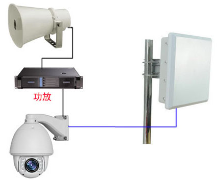
The solution for the voice output part is as follows: Connect the voice output interface of the digital network dome camera to the input interface of the amplifier, and then connect the amplifier to the high-power speakers. Since the monitoring points at the front end and the monitoring center at the back end are on the same local area network, the wireless announcement function from the back-end monitoring center to the front-end can be realized.
The wireless transmission part adopts our company's TQ-5040G digital wireless bridge. This device is equipped with a 18dbi flat antenna, and the transmission distance can reach up to 10 kilometers, fully meeting the wireless signal connection from the front end to the hotspot base station. The transmission performance is stable and reliable. (The specific parameters of the equipment can be found in the attachment.) The switch aggregates the network cameras and other digital devices at the front end and connects them to the data interface of the POE power supply box of the TQ-5040G. These signals are then transmitted to the hotspot-coverage base station via wireless means.
The device connection topology diagram for this section is as follows:
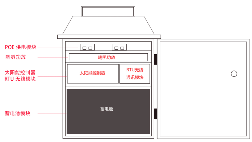
The power supply for the front-end part adopts the solar power supply solution.
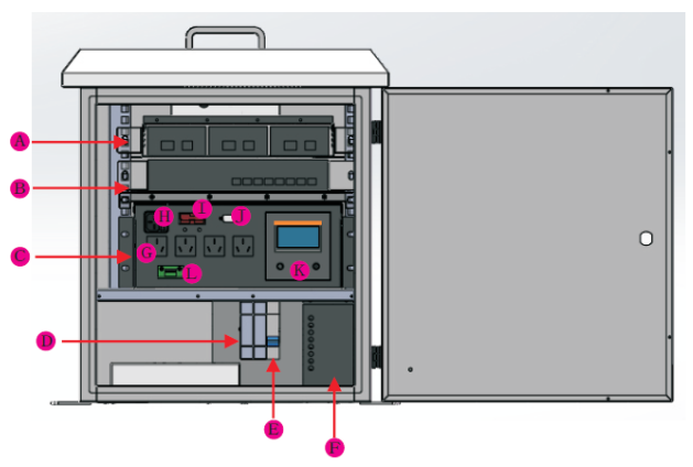
To use a distribution box, inside the box there should be a POE power supply box for the wireless equipment, an RTU wireless communication module, a solar controller and a battery, etc. A 100AH battery should be placed inside the distribution box. At the same time, the solar controller and the inverter should also be placed in the distribution box. The other interface should be connected to a 150W solar panel.
As shown in the figure below:
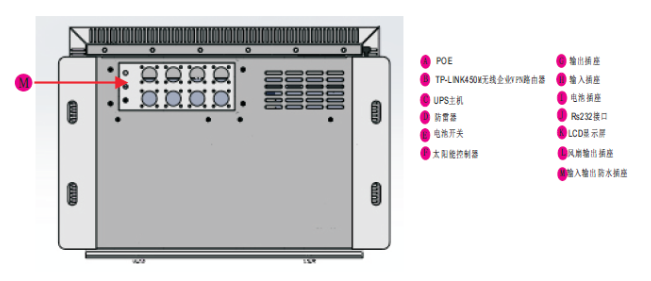
The bottom part is equipped with data and power supply interfaces, which can be connected to speakers, cameras, solar panels and wireless transmission devices, as shown in the following figure:

The overall connection diagram of the key equipment is as follows:

2.2, Wireless Coverage at Relay Points and Point-to-Point Wireless Transmission Section
For the base station relay point part, we adopt our company's high-bandwidth multi-module wireless transmission product, model TQ-5000MS series. The specific model for the product that provides wireless coverage for the base station is TQ-5000MS-02H. The reason for using this equipment as the wireless coverage product is that this product is designed with a gigabit network interface and has a high data processing capability. The equipment itself supports a multi-module design, allowing for the installation of two modules. During the actual hotspot coverage process, if only a omnidirectional antenna is used, the gain is too small and cannot achieve a relatively long transmission distance. Therefore, in the scheme design and product selection, this equipment is used. In one device, two 60-degree antennas can be installed. At this base station, two devices can be installed to install four 60-degree antennas. The combined coverage angle can reach more than 240 degrees, which can basically meet the requirements for connecting the surrounding front-end wireless devices. As shown in the figure below:

Two units of this type of wireless equipment were installed on the tower. Each unit could accommodate two antennas, and the two units could collectively hold four antennas, thus achieving the goal of wireless coverage in the surrounding area.
The relay points also use outdoor distribution boxes to connect the wireless devices.
Design features of the distribution box:
The design adopts a hierarchical structure and is well-organized.
2. All adopt a front-mounted modular installation design, which facilitates installation and subsequent product maintenance.
3. Built-in heat-conducting fan, which balances the temperature between the interior of the cabinet and the outside environment. (The fan can be optionally equipped with a temperature controller. It will start working only when the temperature reaches the set value. Once within the set threshold, the fan will stop operating, thus saving energy.)
4. Optional solar charging converter, which enhances the utilization rate of green energy in environments with sufficient sunlight;
5. Optional installation of a Class D surge protector to ensure the safety of equipment inside the cabinet in harsh outdoor conditions.
6. Long-duration gel batteries can provide a backup time of over 10 hours when the load power is around 100W.
7. Utilizing a sine wave inverter power module, the system can freely switch between mains power and battery power modes, ensuring the continuity of power supply for the load.
8. The inverter power module has a wide voltage range for mains power (140 - 280V) and is connected in parallel with the input mains power, ensuring the safety of the power distribution system.
For point-to-point communication, the wireless equipment we recommend is our TQ-5000MS25. This device is equipped with a 25dBi directional gain antenna. Due to its high transmission power, the transmission distance can reach up to 30 kilometers. As a wireless transmission device between base stations, this equipment has many advantages. It has a built-in gigabit network interface, stable working performance, and the theoretical transmission bandwidth can reach 480 Mbps. The actual measured transmission bandwidth can reach 160 Mbps. This equipment has the characteristic of multi-level relay without loss, which can ensure a high bandwidth data even after multiple relays. The data loss during transmission is very small (the detailed parameters of the above two devices can be found in the product descriptions in the attachment). At the installation location of the base station equipment, the power supply method is the same as the front-end power supply method. Under normal circumstances, it is powered by AC 220V. If in some special situations, there is no city power supply, the above solar power supply system can also be adopted.
Point-to-point distance-free transmission is shown in the following figure:

The distance between hotspots is quite far, so the TQ-5000MS25 is used for directional transmission to ensure that the monitoring data and images from the front end can be stably transmitted to the monitoring center.
