Wireless case study of field geological hazard monitoring
1、 User demand analysis:
The user is a geological disaster reduction monitoring department that needs to install a series of monitoring equipment in an area prone to geological disasters in the wild. At the same time, the data from these monitoring equipment needs to be transmitted to the monitoring command center, which is approximately 40-50 kilometers away from the site. Using wired transmission to transmit monitoring data back requires a significant investment of manpower, material resources, and financial resources. The installation cycle is long and the maintenance cost is high, so this solution is no longer feasible. Therefore, users need to transmit back wirelessly. The on-site situation is as follows:;
The destination is approximately 50 kilometers away from the monitoring center, and the monitored location cannot be directly viewed from the monitoring center (non line of sight). The monitored location has no 4G coverage and no power supply;
It is necessary to monitor the water flow data at the destination location in order to issue warnings when floods occur; Need to monitor landslide data; Real time video monitoring (due to the large amount of data and high transmission bandwidth occupied by video monitoring, as well as the high power consumption of video monitoring cameras, the implementation will be determined based on the on-site situation and solar power supply in the later stage).
2、 Wireless Solution Thinking and Design
Based on the above description of the user's on-site situation, the use of wireless transmission has been determined. However, due to the lack of 4G operator signals on site, 4G devices cannot be used for transmission, and only digital wireless bridges can be used for long-distance transmission. In addition, the monitoring points and relay transmission points at the front end do not have power supply. Therefore, in the design of the scheme, a solar powered solution is needed for power supply, and if necessary, wind turbines can be used for power supplementation.
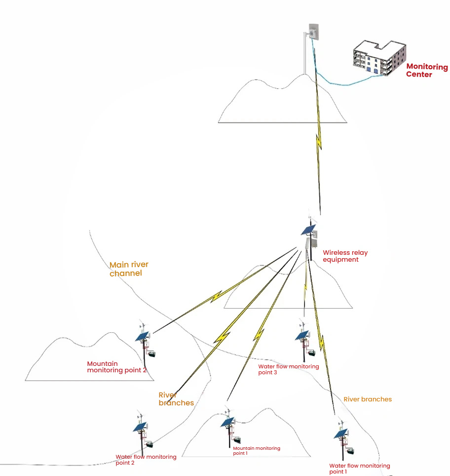
In terms of selecting digital wireless transmission equipment, our company recommends using the following two devices for this application site: SF-5040G series products and SF-5823WJ series products. Based on the user's application site, the wireless transmission topology diagram of the modified solution is shown in the following figure:

According to the above scheme diagram, the wireless devices installed at the front-end valley monitoring points and landslide monitoring points are generally installed at relatively low positions and cannot directly see the remote monitoring command center. Therefore, a relatively high position needs to be selected as a relay transmission point around some nearby monitoring points. First, the data from the front-end monitoring points is collected by wireless devices to the relatively high relay transmission point, and then transmitted to the nearby higher mountains of the back-end monitoring center through a pair of long-distance digital bridges. Then, it is transmitted to the monitoring command center through wired means.
The two digital wireless transmission devices used by our company can meet the transmission requirements in the above solution. SF-5040G is a medium to short-range wireless transmission device suitable for transmitting and summarizing front-end monitoring data to relay transmission points for use as branch line aggregation equipment. After summarizing the monitoring data from the front-end, the remote device SF-5823WJ, equipped with a high gain directional antenna, transmits the data to the monitoring command center 50 kilometers away.
Equipment required for nodes:
Water flow monitoring points 1, 2, 3: TQ-5040G, integrated wind solar power generation storage system, water flow data acquisition sensor;
Mountain monitoring points 1 and 2: TQ-5040G, integrated wind solar power generation and storage system, mountain data acquisition sensor;
Wireless relay point: TQ-5040G-W, angle antenna TQ-5823WJ、 Dish antenna, switch, integrated wind solar power generation and storage system;
Monitoring Center: TQ-5823WJ, Dish Antenna
Implementation process:
The water flow monitoring point and mountain monitoring point use SF-5040G to transmit the data collected by the sensors to the wireless relay device point located at the high point. At the wireless relay device point, SF-5040G-W is used in conjunction with an external angle antenna to receive sensor information from the water flow and mountain monitoring points; Then, the information is connected to the remote wireless bridge SF-5823WJ through a switch for transmission. A similar SF-5823WJ is set up at the highest receiving point 50KM away (the transmission path of the paired SF-5823WJ device is unobstructed), and the received information is transmitted to the monitoring center using data cables or optical fibers.
In this plan, if a real-time video surveillance system is considered to be added in the later stage, cameras can be added to the monitoring points and video storage devices can be added to the monitoring center on the basis of the existing wireless network, without the need for additional transmission equipment.


