


The Application of IP Mesh Radio in Military and Unmanned Aerial Vehicle (UAV) Communications
2025-10-28


In order to keep up with the times, our company has been constantly developing new products to meet the market demands. The latest OFDM two-way wireless transmission link equipment we have developed uses 1.4G as the central frequency point. It features two-way data transmission, strong anti-interference ability and long transmission distance. To further verify its performance, our company conducted outdoor field tests in Huizhou. After the tests, the performance of the equipment exceeded the design expectations and it will be officially launched to the market soon.
The following are some photos and data from the on-site tests:
I. Test on Huizhou Petrochemical Avenue
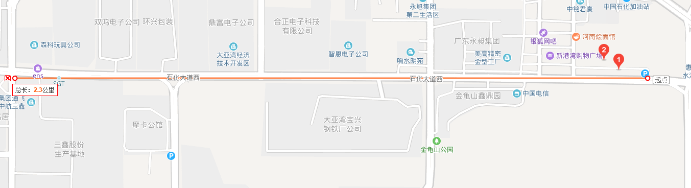
Test environment: Located on the western section of Petrochemical Avenue in Daya Bay, Huizhou. The road is basically straight and flat, with a green belt and trees in the middle, and tall buildings on both sides. Buses, trucks, and cars pass by on the road from time to time.
Placement at the transmitting end:
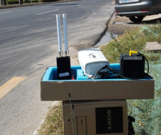
The transmitting antenna is placed on a 40 cm high cardboard box located on the roadside.
Receiving end placement:
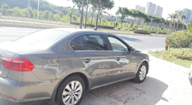
The receiving antenna is placed on the roof of the car (about 1.5 meters above the ground). The transmitting end is fixed, while the receiving end moves along the road.
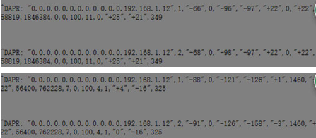
1. Test the 25dBm transmission power. Both ends are equipped with 45cm-long small suction cup antennas.
Test result: The video was smooth at 950 meters, and remained smooth at 1160 meters. At this point, the access node reported (to the mobile video receiving end):
Main antenna SNR: 0
Auxiliary antenna SNR: +3
Conclusion:25 dBm transmission power, the distance from the ground to the vehicle roof can reach 1160 meters,When there is a significant obstruction (such as a large bus) between the transmitting and receiving antennas, especially when the obstruction is located near the transmitting and receiving antennas along the transmission path, the video signal will be interrupted.
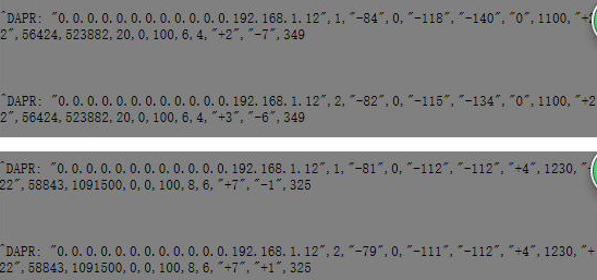
2. Test the 2W transmission power. The access node transmits the video, and the vehicle is the central node receiving the video. The antenna placement condition remains unchanged.
A. Test data using small suction cup antennas at both ends:
Due to the fact that from time to time large vehicles would block the receiving antenna behind the test vehicle or pass by the road surface in front of the transmitting end, the above test data were not regular.
When the test distance reached 2.2 kilometers, the video was smooth (with a bitrate of around 3.8 MBps).
B. Replace both ends with small fiberglass antennas (about 16 cm in length) and test the data:
When the test distance reached 1.2 kilometers, the video was smooth (with a bitrate of around 3.8 MBps).
C. Test data when both ends are replaced with small rubber tube antennas:
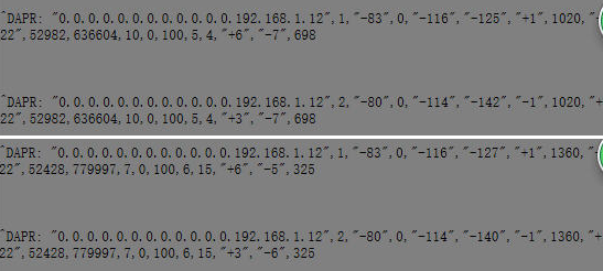
When the test distance reached about 1.3 kilometers, the video was smooth (with a bitrate of around 3.8 MBps).
D. Transmission power: 2W. Both ends are rubber-coated antennas. However, the transmitting antenna is raised to a height of approximately 1.5 meters above the ground. Data:
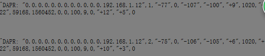
At the same distance, when the height of the transmitting antenna from the ground is raised to around 1.5 meters, the SNR value improves.
Conclusion:
● 300mW (25dBm) transmission power. One end of the small suction antenna is placed 40 cm above the ground, and the other end is placed 1.5 meters above the ground. Without large obstructions, there is no problem with a distance of about 1.1 km.
● 2W transmission power. One end of the small suction cup antenna is placed 40 cm above the ground, and the other end is placed 1.5 meters above the ground. Without any significant obstructions, there is no problem with a distance of about 2.2 km.
● 2W transmission power. One end of the small fiberglass antenna or rubber rod antenna should be placed 40 cm above the ground, and the other end should be placed 1.5 meters above the ground. Without any large obstructions, a distance of about 1.3 km is acceptable.
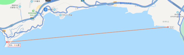
Between Damaisha in Shenzhen and Dapeng Bay
The access node (video transmitting end) is located at the Jiuhekou Overseas Chinese Cemetery in Damaisha, with an altitude of about 80 meters. The receiving end is at Guanhu Beach in Damaisha, 8,530 meters away. The transmitting end uses a glue stick antenna, and the receiving end uses a small suction cup antenna placed on the rocks on the beach, with an altitude of 2 to 3 meters.
The reported data from the access nodes obtained during the test and the speed measurement data of the wireless link:
At a distance of 8530 meters, the SNR of the main and auxiliary antennas of the access node (video transmitting end) is still around 9 to 11. The wireless link rate can be stably measured at 12 Mbps and 15 Mbps. At this time, the SNR of the main and auxiliary antennas of the central node (video receiving end) is around 6 to 8 (there are many grocery stores near the test point, and the background noise is not as good as that of the transmitting end)
Conclusion:
2W transmission power, the altitude of the transmitting end (access node) is 80 meters (rubber rod antenna), the altitude of the receiving end (central node) is within 3 meters (small suction cup antenna), the distance is 8530 meters, the wireless link rate can reach 15 Mbps (bit error rate 0%), the transmission end SNR is 9 to 11, and there is still great potential to cover even longer distances.