


The Application of IP Mesh Radio in Military and Unmanned Aerial Vehicle (UAV) Communications
2025-10-28


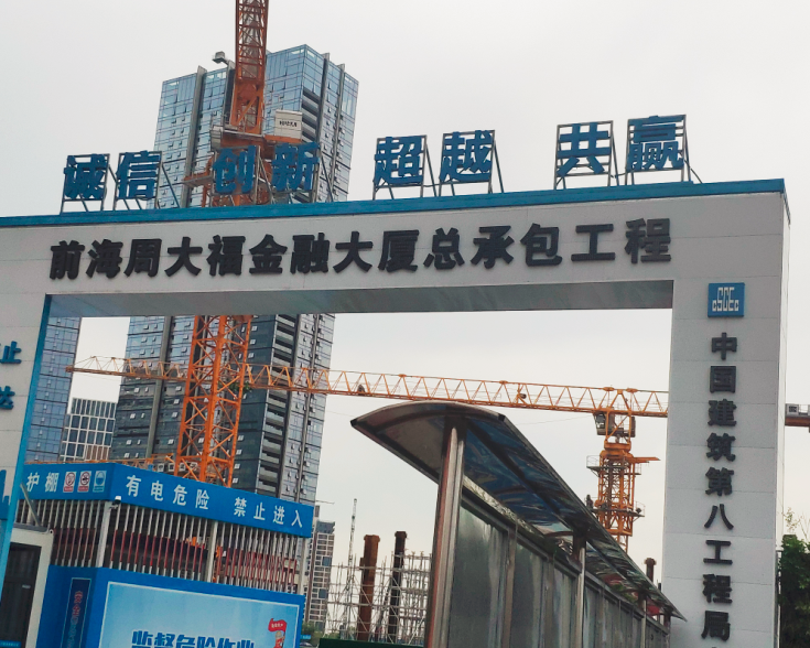
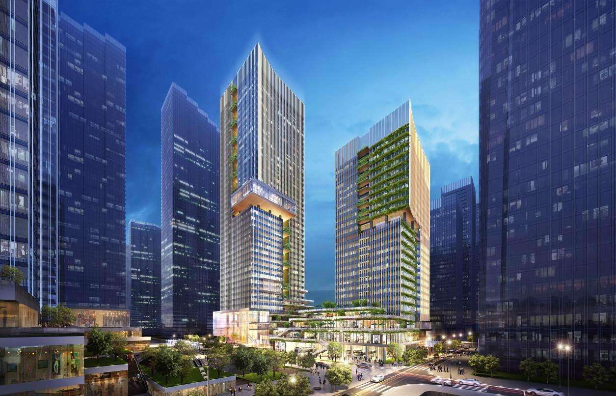
This project is located in the core area of Guiwan District in the Qianhai Free Trade Zone of Shenzhen. It is situated at the exit of Guiwan Metro Station. The building will feature two landmark twin towers with heights of approximately 220 meters and 130 meters. It will also include commercial spaces, art exhibitions, green parks, and performance venues as配套设施. In the future, this project will attract world 500-strong foreign financial institutions to set up regional headquarters here, positioning it as a world-class financial business and service complex. The project's renderings are as follows:
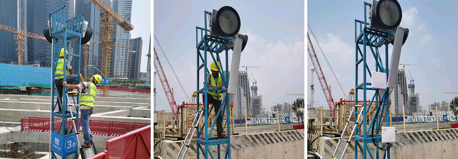
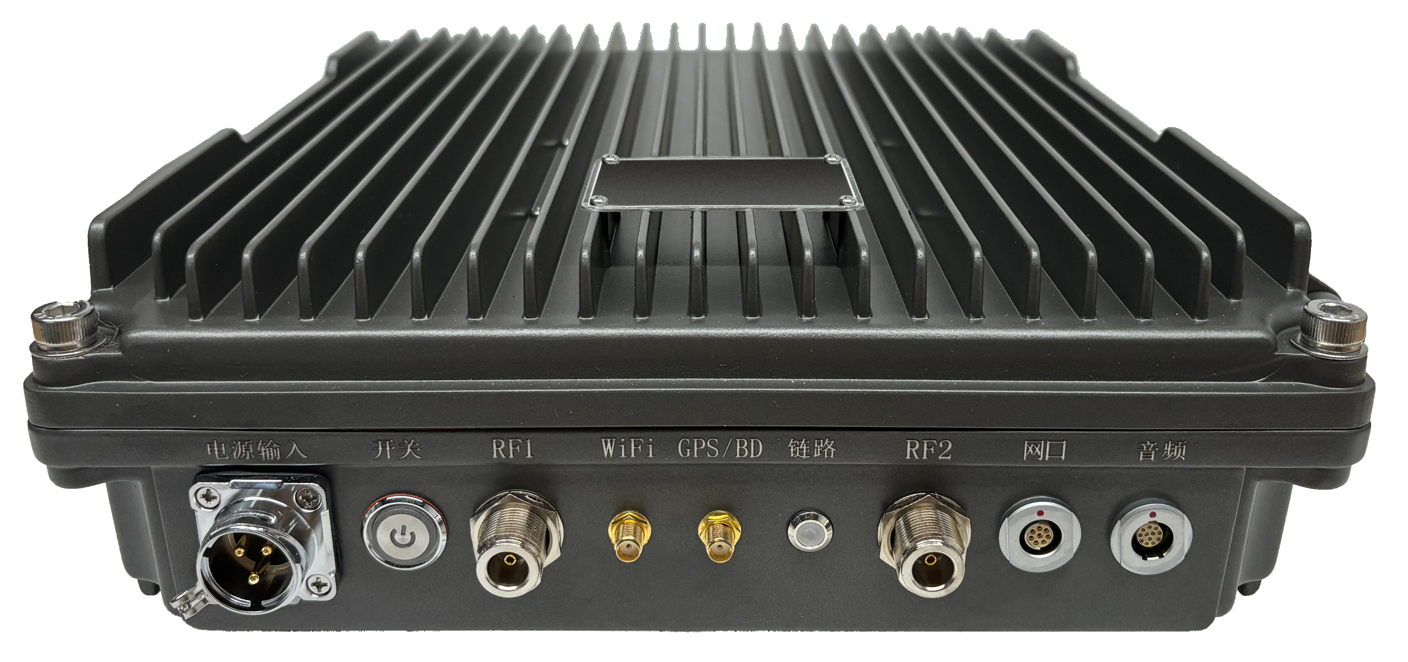
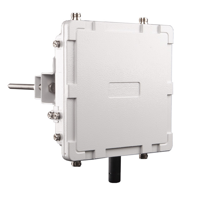
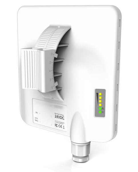
During the project construction process, in order to support the intelligent and informatization construction of the construction site, the wireless ad hoc network base station equipment TQ-5800M provided by our company has provided product support for the on-site network coverage. After on-site installation and testing, all indicators have met the customer's requirements. The following are the on-site construction pictures: