


What Is an IP Mesh Radio and How Does It Work?
2025-10-24


The advantages of wireless monitoring are indeed numerous in practical projects. However, in many cases, wireless monitoring still frequently encounters some problems. Of course, with the development, many projects will adopt wireless monitoring equipment to establish wireless monitoring systems. So, when it comes to building a high-definition wireless monitoring system, what aspects should we pay attention to?

I. Image shooting quality
The image quality of millions of high-definition network cameras is just as important as that of ordinary surveillance cameras. As for whether to choose standard definition or high definition, it should be decided by the property owner or the customer themselves. All we need to do is to show the effect of the camera images.
II. Audio Function of Network Monitoring Project
The decision will be made based on the actual situation of the project. If an audio-capable million-pixel high-definition network camera is to be adopted, then the issue of whether to connect headphones or speakers, microphones, and other devices also needs to be considered.
III. Transmission Environment
Wireless bridges use microwave signals to transmit video and other data. Therefore, it is necessary to ensure that the wireless bridge operates in an open and unobstructed environment for signal transmission, so as to ensure the stable transmission of wireless monitoring equipment in the wireless monitoring system and maintain the stability of the wireless monitoring system. The installation location of the wireless bridge should be chosen in areas where signal transmission is smooth as much as possible.
IV. Selection of Aggregation Layer Switches
The number of IPCs that can be connected by a single front-end switch does not exceed 4. An 8-port 100Mbps switch can be used. If the number exceeds 4, an 8-port 1000Mbps switch must be adopted. The connection between the front-end switch and the main switch in the server room should be made via network cables or optical fibers. If the number of IPCs under load is too large, packet loss, frame dropping, delay, and stalling phenomena are likely to occur.
Note: When setting up a wireless monitoring system, the switch used must be a dedicated monitoring switch. It is not allowed to use a regular switch for transmitting signals from the ordinary transmission network.
V. Make sure to record the address accurately
Before the construction, it is necessary to uniformly modify and register the IP addresses of all the network cameras, network video recorders, wireless bridges, NVRs, main computers, storage servers, streaming media servers, high-definition decoders, management servers, etc. in this system. Be sure to pay attention to avoiding IP address conflicts with the original devices in the local network (such as computers, network printers).
VI. Be cautious of IP address conflicts
The IP addresses of all devices connected to the wireless network must not conflict with each other. For example, IP addresses of network cameras, wireless bridges, NVRs, computers, and all other network devices must not be the same, but they must be within the same local area network.
VII. Pay Attention to the Selection of Network Cables
For a 100-megabit switch, Category 5e network cables are typically used. For a 1-gigabit switch, Category 6 cables are preferred. As for whether to use unshielded or shielded cables, this is not very crucial. If the client specifically requests high-quality ones, then low-smoke, halogen-free 6-category shielded cables would be the choice.
I. Hardware Installation
Since all the wireless bridge devices are powered by POE, it is extremely important to correctly connect the POE power supply box, wireless bridge, IP camera, etc. The wireless bridge devices all adopt outdoor waterproof and dustproof designs, and corresponding waterproof and dustproof measures should be taken at the network cable connection points.
1. Implement rainproof and dustproof measures. For the network cables connecting the wireless bridge, POE, and network cameras, ensure they are properly protected against rain and dust. The connection points between the network cables and the wireless bridge usually require two to three layers of waterproof tape to be wrapped around them, and it is best to keep the crystal connectors hidden; the connection points between the network cables and the network cameras also need to be wrapped with two to three layers of waterproof tape or insulating tape; all power connection points should be insulated as much as possible.
2. Installation and fixation of wireless bridge equipment. When installing the wireless bridge, the first step is to securely fix the support. If the support is unstable, it will directly affect the stability of microwave signal transmission. When fixing the wireless bridge onto the support, follow the fixation method shown in the figure to ensure a firm attachment. During the installation process, since the surface of the support is relatively smooth, if you directly tighten the U-shaped clamp with a nut, over time, the outdoor rainwater may penetrate the surface of the support and cause rust, and the contact between the U-shaped clamp and the support will become loose. During installation, it is necessary to place an elastic ring on the support to ensure close contact between the U-shaped clamp and the elastic ring.
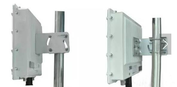
During installation, it is necessary to align the antenna of the device properly to ensure high sensitivity in signal reception and stable transmission of signals. As shown in the following picture:

3. Control of Network Cables and Length. To extend the distance between the wireless bridge and the power supply box or switch, there are two options for the network cables: CAT5e (ultra-5) or CAT6 (ultra-6). The requirement for the network cables is either CAT5e or CAT6. Since the wireless bridge uses POE (Power Over Ethernet) for power supply, the network cables not only transmit data but also supply power to the wireless bridge. Therefore, if the network cables are too long or of poor quality, they will cause significant attenuation. The connection part between the wireless bridge and POE should use CAT5e or higher (preferably choose branded network cables), and the length should be controlled within 25 meters.
Note: When using CAT5e or CAT6 cables to transmit data over a distance of 100 meters, it refers to the distance from the LAN port of the POE power supply box to the camera or switch being 100 meters (as shown in Figure 1); however, due to different on-site environments, the POE power supply box may be installed in a distribution box located farther away from the monitoring center or the computer room. In such cases, it is advisable to use optical fiber transmission from the POE power supply box to the monitoring center or the computer room (as shown in Figure 2).

The network cables connecting the wireless bridge and the POE device should not be too long. It is recommended to use CAT5e or CAT6 cables, and the length should not exceed 25m to avoid insufficient power supply. The network cables connecting POE to devices such as network cameras, switches, and NVRs should not exceed 100m to prevent network signal attenuation. As shown in Figure 2:

When the data transmission port of POE is located far away from the monitoring center or equipment in the computer room (more than 100 meters), it is recommended to use optical fiber transmission.
Currently, the two main types of POE recommended for use are: one is the modular POE that receives external DC power input, and the other is the regulated POE that integrates a transformer internally and uses an input of 220V AC voltage (as shown in Figure 3). Special attention: Regardless of which type of POE is used, the interface definitions are uniform. The network port marked with "DATA IN" on the POE can be connected to network cameras, switches, computers and other network devices, while the network port marked with "P + DATA OUT" must be connected to wireless bridge equipment. When connecting, be careful not to make a wrong connection and damage the equipment.

4. Correct connections of network devices such as wireless bridges, POE power supply boxes, network cameras or switches. The POE power supply box usually has three interfaces: a power input interface (generally DC input), a POE network interface (only used to connect the RJ45 port of the wireless bridge device), and a network interface or LAN interface (can be connected to any network device based on the Ethernet port, such as: network cameras, switches, routers, computers, NVRs, etc.).
5. Network cable manufacturing standards and type selection. The current manufacturing standards for network cables are generally based on the definitions of national standards. It is recommended to use the mainstream T568B wiring standard for manufacturing network cables. The standard is as follows:
T568B: White Orange, Orange, White Green, Blue, White Blue, Green, White Brown, Brown
The wireless bridge equipment is powered by POE. It is recommended to use the standard T568B wiring sequence for the network cable. Since all network devices have adaptive Ethernet ports, when connecting the wireless bridge equipment to POE or connecting the POE to the switch, it is strongly recommended to use straight-through cables (i.e., both ends of the network cable have the standard T568B wiring sequence).
6. Lightning protection. Wireless bridge equipment is usually installed in outdoor open areas, so it is necessary to take lightning protection measures; The equipment itself has the correct IP address for planning the wireless bridge. The wireless transmission system formed by using wireless bridges will use a large number of IP addresses. To avoid conflicts between the IP address of the wireless bridge equipment and the IP addresses of other devices in the local area network, there are mainly two solutions:
First, separate into independent networks. Separate the wireless transmission network formed by the wireless bridge from other networks (such as the office network, server network), and use a separate core switch for it.
Second, re-plan the IP addresses of the devices. Separate the IP addresses of the wireless bridge device from those of the network cameras and the hard disk recorder into different network segments.
The lightning protection circuit is provided with a lightning protection grounding terminal (GND) on the outside of the equipment. The correct method for lightning protection grounding is as follows: The pole for fixing the wireless bridge usually has a lightning rod installed. The grounding terminal of the wireless bridge needs to be connected to a copper core wire (generally 4mm in diameter) and connected to the lightning line to be grounded to the earth.
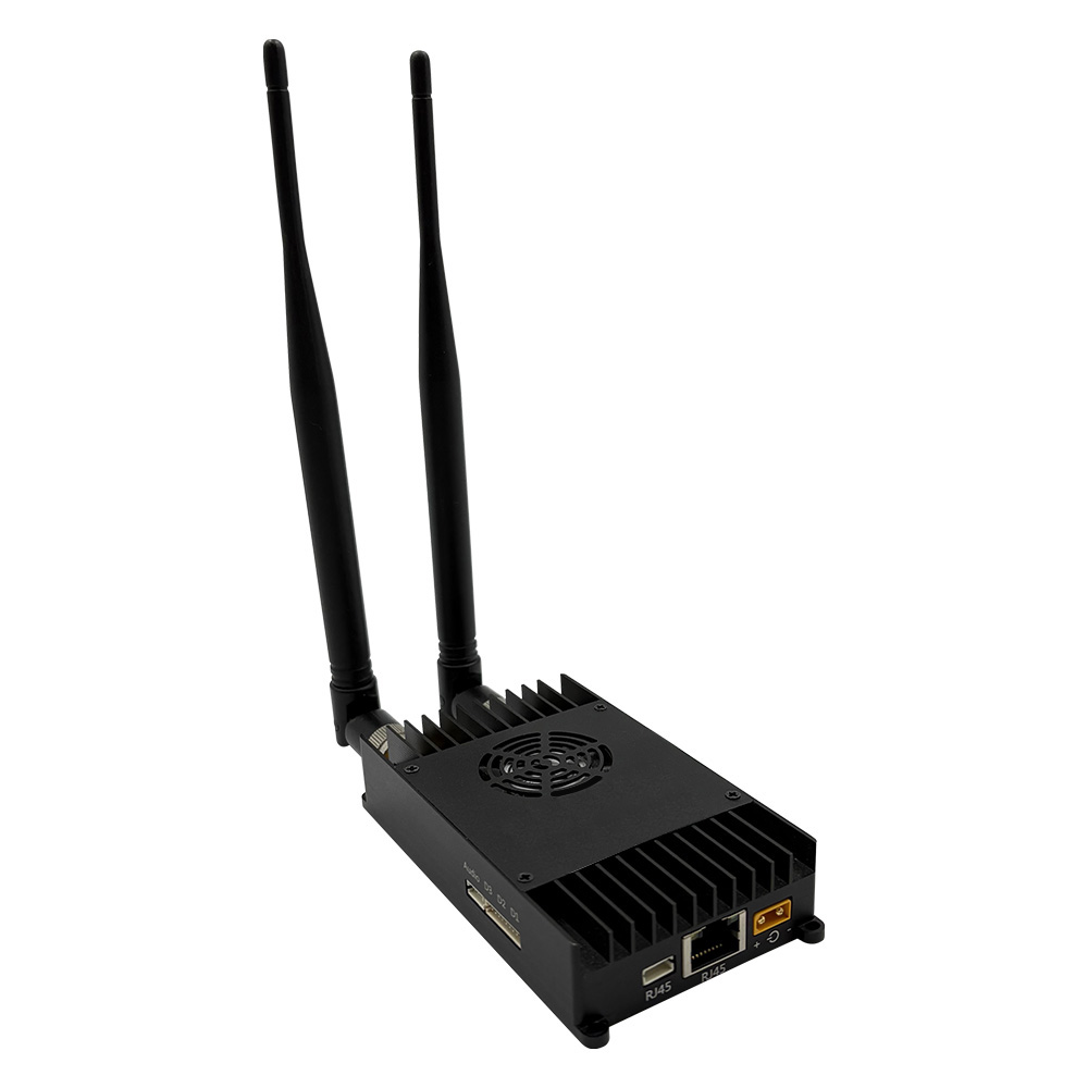
7. Handling of feeder connector. For outdoor high-power bridge equipment, since the transmission distance is long and an external antenna needs to be installed, a feeder connection is required between the antenna and the equipment. At this time, all the connector parts of the feeder connecting the equipment and the antenna must be treated for rainproof and dustproof. Two to three layers of waterproof or insulating tape should be wrapped around them, and it is best not to leave the feeder connector part exposed in the air.
II. Software Debugging Precautions
The configuration of wireless bridge devices is carried out through the software interface of IE browser to modify or adjust relevant parameters in order to achieve the best transmission effect. Since each wireless bridge comes with the corresponding software debugging manual when manufactured, we will not elaborate on this again. However, we will briefly explain some problems that may be encountered before the debugging.
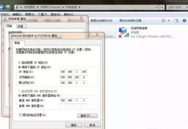
1. The debugging of wireless bridge equipment requires entering the software debugging interface of the device through a browser (such as Internet Explorer, 360 Browser, Sogou Browser, etc.). First, the IP address of the local computer needs to be changed to ensure that the IP address of the device is in the same network segment as that of the local computer. The specific operation is as follows: Open "Control Panel" - "Network and Sharing Center" - "Change Adapter Settings" - "Local Connection" - "Properties" - "Internet Protocol Version 4 (TCP/IPv4)" and manually set the IP address of the computer.
2. After setting the IP address, enter the device's IP address in the address bar of the browser. Since this is the first time accessing the debugging interface of the bridge device, after typing in the device's IP address and pressing Enter, the browser may not directly pop up the login interface of the device. Instead, a line of English text will appear on the main interface of the browser (Press after all configurations to enable new settings). “Reboot”
There is no need to suspect that this phenomenon is caused by equipment or computer issues. The reason for such problems is usually a compatibility issue caused by using a third-party browser. In this case, simply click the mouse on the right side of the browser address bar to switch the browser mode (compatibility mode or speed mode) and it will solve the problem.
3. Properly allocate the IP addresses for the wireless bridge. The wireless transmission system set up using the wireless bridge will require a large number of IP addresses. To prevent conflicts between the IP addresses of the wireless bridge device and those of other devices within the local area network, there are two main solutions: First, separate into an independent network. Separate the wireless transmission network set up by the wireless bridge from other networks (such as the office network, server network), and use a separate core switch for it; Second, re-plan the IP addresses of the devices. Divide the IP addresses of the wireless bridge device and network cameras, as well as those of the hard disk recorder, into different network segments.